Quick answer
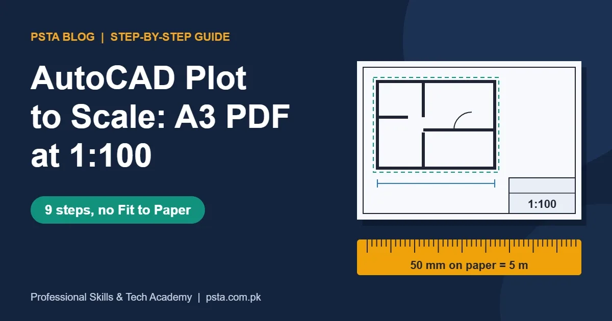
To plot to scale in AutoCAD, draw at real size and switch to a layout. In Page Setup, choose a PDF driver, A3 paper, plot area Layout and a 1:1 scale. Set the viewport to 1:100, lock it, preview and plot. Then measure a known dimension on the PDF to confirm the scale.
Key takeaways
- • Plot layouts at 1:1 and give each viewport its own exact scale, such as 1:100.
- • Avoid Fit to Paper for any sheet someone will measure with a scale ruler.
- • Check the sheet size first: a 12 m × 20 m plan fits A3 at 1:100 but needs A2 at 1:50.
- • Lock the viewport after scaling so an accidental zoom can't change it.
- • Use a monochrome CTB for black prints and replace True Color objects with index colors.
- • Measure one known dimension on the finished PDF before you send it.
Table of contents 20 sections
- What Does "Plot to Scale" Mean in AutoCAD?
- Model Space or Layout: Where Should You Plot From?
- Paper Sizes and the Scale Math to Do First
- AutoCAD Plot to Scale: The 9-Step Method
- Step 1: Confirm Your Drawing Units
- Step 2: Open a Layout Tab and the Page Setup Manager
- Step 3: Pick a PDF Driver and Paper Size
- Step 4: Choose Layout as the Plot Area at 1:1
- Step 5: Choose the Plot Style Table and Lineweights
- Step 6: Insert a Title Block and Draw the Viewport
- Step 7: Give the Viewport an Exact Scale
- Step 8: Pan Into Position and Lock the Viewport
- Step 9: Preview, Plot and Measure the PDF
- Which Plot Style Table Should You Use: CTB or STB?
- Feet-and-Inch Drawings: Using Imperial Scales Correctly
- Line Types and Text That Look Wrong After Scaling
- Plotting a Full Set of Sheets to One PDF
- Why Does My PDF Print at the Wrong Size?
- Practice Plotting in PSTA's AutoCAD Course
- Measure Your Last PDF Today
An example from a drafting desk: a civil engineering student finishes a ground floor plan, clicks Plot, picks Fit to Paper and sends the PDF to a print shop in Abbottabad. The supervisor lays a scale ruler on the A3 print, and nothing measures right. The fix is to learn the AutoCAD plot to scale method once: set up a layout at 1:1, give the viewport a real scale such as 1:100, and plot the layout. It takes about ten minutes the first time and two minutes after that.
This guide walks through that method with metric and feet-and-inch examples. Here is what you'll be able to do after reading it:
- Explain the difference between plot scale, layout scale and viewport scale
- Work out which sheet size a plan needs before you open the Plot dialog
- Produce an A3 PDF at 1:100 that measures correctly with a scale ruler
- Choose between a CTB and an STB plot style table for black-and-white prints
- Diagnose the usual reasons a PDF comes out the wrong size
What Does "Plot to Scale" Mean in AutoCAD?
In AutoCAD you draw real objects at their real size. A 4,500 mm wall is drawn 4,500 units long, not shrunk to fit a page. Scaling only happens at the output stage, when AutoCAD maps drawing units onto paper millimeters or inches.
Autodesk's help page About Setting the Plot Scale describes the ratio plainly. If your paper is in millimeters and you enter 1 mm = 10 units, each printed millimeter stands for 10 real millimeters. That is a 1:10 drawing.
A scale of 1:100 therefore means one millimeter on paper equals 100 mm in the building. A 10 m room prints 100 mm long. Anyone with a scale ruler can check your sheet, and that is the whole point of a scaled drawing.
Fit to Paper does something different. It makes the drawing as large as the sheet allows, so the ratio becomes an odd number that no scale ruler matches. Autodesk suggests it for drafts where precise scale matters less. That's fine for a check print, but not for a sheet someone will measure.
Model Space or Layout: Where Should You Plot From?
You can plot from either, but they behave differently.
Model space plotting uses one scale, typed into the Plot dialog. It works for a quick single view. The trouble starts when you need a title block, notes and two views at different scales on one sheet.
Layout plotting uses two scales, as Autodesk's plot scale page explains. The layout itself is plotted at 1:1 because it already represents the paper. Inside it, each viewport has its own model scale. Your title block, sheet border and general notes sit on the layout at their printed size, and the floor plan shows through a viewport at 1:100.
For any drawing you'll submit, hand to a contractor or put in a portfolio, use a layout. Every AutoCAD plot to scale job in the rest of this guide assumes you do.
Paper Sizes and the Scale Math to Do First
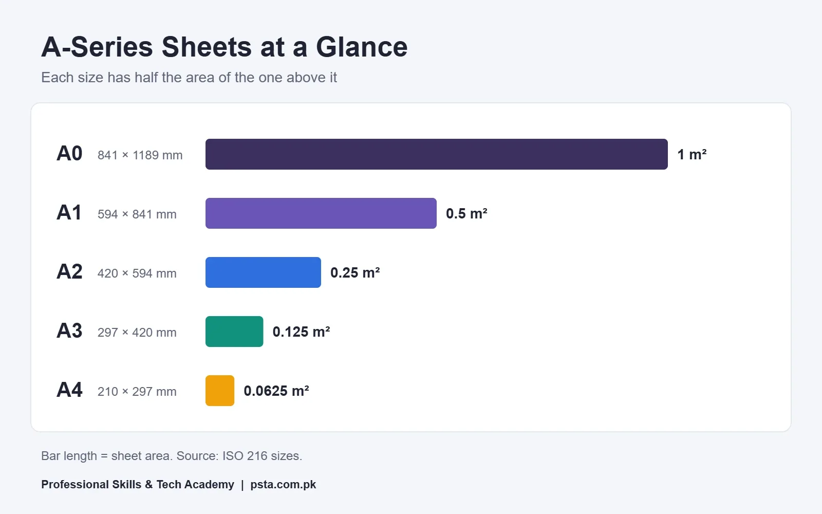
Most plotting problems start with the wrong sheet, so check the fit before touching any settings. The A-series sizes are fixed by ISO 216. Markus Kuhn's reference page on ISO paper sizes lists them: A0 is 841 × 1189 mm with an area of one square meter, and each smaller size has half the area of the one before it.
| Sheet | Size (mm) | Approximate area |
|---|---|---|
| A0 | 841 × 1189 | 1 m² |
| A1 | 594 × 841 | 0.5 m² |
| A2 | 420 × 594 | 0.25 m² |
| A3 | 297 × 420 | 0.125 m² |
| A4 | 210 × 297 | 0.0625 m² |
Now divide the building size by the scale. Take a footprint of 12 m × 20 m:
- At 1:100 it prints 120 × 200 mm. That fits on an A3 sheet with its long side across (420 × 297 mm) with plenty of room for a title block and notes.
- At 1:50 it prints 240 × 400 mm. That technically squeezes onto A3, but leaves no space for a border or title block. Move up to A2.
The table below shows how one meter of building prints at common metric scales. Keep it next to your keyboard until the numbers become automatic.
| Scale | 1 m in the model prints as | Text 2.5 mm on paper needs this model height (non-annotative) |
|---|---|---|
| 1:20 | 50 mm | 50 mm |
| 1:50 | 20 mm | 125 mm |
| 1:100 | 10 mm | 250 mm |
| 1:200 | 5 mm | 500 mm |
| 1:500 | 2 mm | 1,250 mm |
The third column explains a common surprise. Text written in model space at 2.5 mm height disappears on a 1:100 print, because it shrinks a hundred times. Either multiply text height by the scale, or use annotative text, which Autodesk says is sized by the current annotation scale so it prints correctly.
AutoCAD Plot to Scale: The 9-Step Method
The AutoCAD plot to scale steps below use a metric plan drawn in millimeters and an A3 PDF. The command names are the same in AutoCAD and AutoCAD LT.
Step 1: Confirm Your Drawing Units
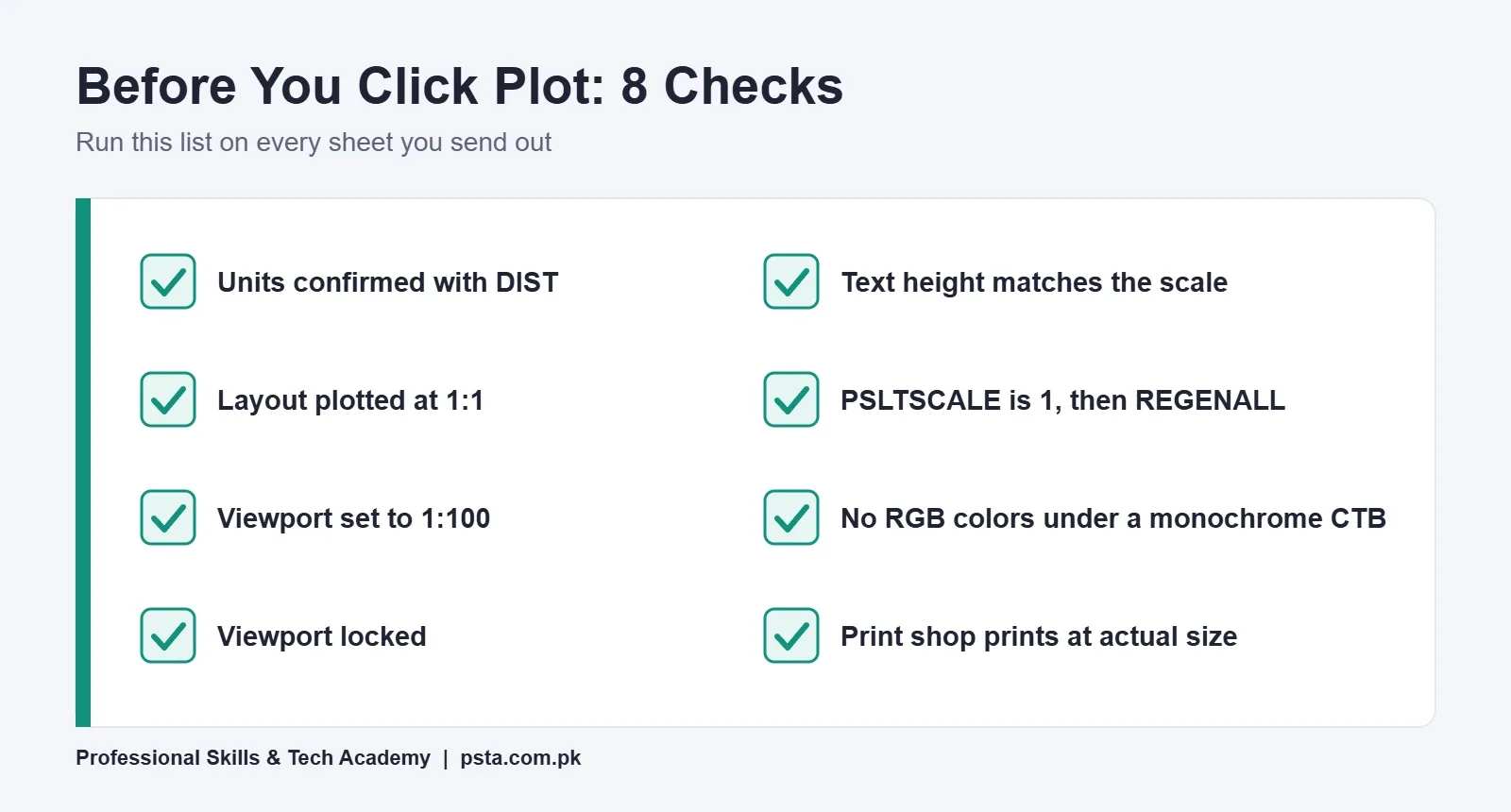
Type UNITS and check the insertion scale. Then measure one known item with DIST. If a 1,200 mm window measures 1.2, you drew in meters, and every scale in this guide changes by a factor of 1,000. Fix the units decision before plotting, not after.
Step 2: Open a Layout Tab and the Page Setup Manager
Click the Layout1 tab, right-click it and rename it to something useful, such as GF-PLAN. Then type PAGESETUP and click Modify. Settings saved here stay with the layout, so you won't repeat them on the next print.
Step 3: Pick a PDF Driver and Paper Size
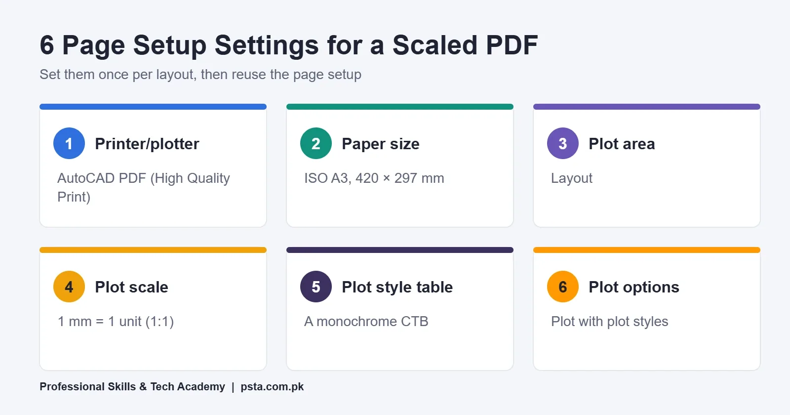
Under Printer/plotter, choose a PDF configuration. Autodesk's PDF export page lists four AutoCAD PDF presets. High Quality Print suits drawings headed for paper. Smallest File suits email. Web and Mobile keeps hyperlinks working. General Documentation covers most other uses. Then select an ISO A3 paper size of 420 × 297 mm and set the orientation to Landscape.
Step 4: Choose Layout as the Plot Area at 1:1
Plot area should read Layout. Set the scale to 1 mm = 1 unit. Fit to Paper is greyed out when Plot Area is Layout, according to Autodesk's plot scale page, and that's a useful safety catch. The layout is the paper, so it always plots at 1:1.
Step 5: Choose the Plot Style Table and Lineweights
Pick a plot style table under Plot style table (pen assignments). For black-and-white prints, a monochrome CTB is the usual choice. Under Plot options, keep Plot with plot styles ticked. The Page Setup dialog reference notes that this option also turns on Plot object lineweights. Click OK and close the manager.
Step 6: Insert a Title Block and Draw the Viewport
Draw or insert your border and title block on the layout at real paper size. An A3 border might sit 10 mm inside the sheet edge. Delete the default viewport if it's in the wrong place, then use MVIEW to draw a new rectangle inside the border. Put viewports on their own layer, such as VPORT, and set that layer to No Plot so the frame doesn't print.
Step 7: Give the Viewport an Exact Scale
Select the viewport border and pick 1:100 from the Viewport Scale list on the status bar. You can do the same through the Properties palette or the triangular scale grip. A keyboard option also works: double-click inside the viewport, type ZOOM, then 1/100XP. Autodesk's page About Scaling Views in Layout Viewports lists all four methods and adds one detail: stretching the viewport border never changes the scale.
Step 8: Pan Into Position and Lock the Viewport
While inside the viewport, use PAN only, never the mouse wheel, to center the plan. Then double-click outside the viewport, select its border and click the Viewport Lock button on the status bar. A locked viewport can't change scale through an accidental zoom, and that's a frequent way a correct sheet goes wrong the night before a deadline.
Step 9: Preview, Plot and Measure the PDF
Type PLOT, confirm the page setup name, click Preview and check that nothing is clipped. Save the PDF. Then open it, find a known dimension such as a 5,000 mm wall and measure it with your PDF reader's measuring tool or a ruler on a printed copy. At 1:100 it should read 50 mm. If it does, your sheet is correct.
Which Plot Style Table Should You Use: CTB or STB?
A plot style table decides how each object prints: its color, lineweight and screening. Autodesk's About Plot Style Tables page describes two kinds.
| Feature | Color-dependent (CTB) | Named (STB) |
|---|---|---|
| How it decides | By object color | By a named style on the object or layer |
| Number of styles | 256, one per color | As many or as few as you need |
| Add or delete styles | No, only edit them | Yes |
| Same color, different print | Not possible | Possible |
| Good fit for | Students and most small offices | Firms with a strict CAD standard |
Start with a CTB. It's simple and most drawings you receive from others will expect one. One warning from an Autodesk support article: objects given a True Color (RGB) value can still print in color under a monochrome CTB, because a CTB only maps the 256 index colors. If a few lines come out blue on your "black" PDF, check their color for an RGB value and switch it to an index color.
Feet-and-Inch Drawings: Using Imperial Scales Correctly
If your plans are dimensioned in feet and inches, the method stays the same, but you pick imperial scales. Two common ones are 1/8" = 1'-0", which equals 1:96, and 1/4" = 1'-0", which equals 1:48. The math is simple: one foot is 12 inches, so 1/8 inch per foot is 1 to 96.
Here is a worked case. A plot of 35 ft × 65 ft at 1/8" = 1'-0" prints about 4.4 × 8.1 inches, roughly 111 × 206 mm. That fits on A3 with space left for a schedule.
The trap is mixing units. When the model is drawn in inches, keep the page setup paper units in inches as well, so the imperial entries in the viewport scale list mean what they say. A model drawn in inches viewed through a 1:96 viewport on a millimeter layout prints 25.4 times too small.
Line Types and Text That Look Wrong After Scaling
Dashed and center lines often print as solid lines on a scaled viewport. The system variable PSLTSCALE controls this. Autodesk's PSLTSCALE reference says that at its default value of 1, dash lengths in viewports follow paper space units, so viewports at different scales show identical dashes. LTSCALE still adjusts the overall dash length.
After changing either value, type REGENALL. The page notes that existing viewports don't refresh on their own, which is why the change can look like it failed.
For text and dimensions, choose one approach per drawing. Either scale them by hand using the table earlier, or use annotative styles and set the annotation scale to match the viewport. Mixing both methods on one sheet leads to tiny notes beside oversized dimensions.
Plotting a Full Set of Sheets to One PDF
A house drawing set usually has a site plan, floor plans, elevations and a section. Plotting each layout separately creates a folder full of files. Autodesk's PDF export page describes two better commands:
EXPORTPDFexports all layouts of the current drawing to one PDF.PUBLISHlets you choose specific layouts, including layouts from several DWG files, and combine them into one multi-sheet PDF.
Each layout uses its own saved page setup, so the work you did in Steps 2 to 5 pays off here. Clear layout tab names also make the sheet list easier to check before you publish.
Why Does My PDF Print at the Wrong Size?
When an AutoCAD plot to scale attempt doesn't measure correctly, the cause is usually one of these.
| Symptom | Likely cause | Fix |
|---|---|---|
| Scale ruler reads wrong by a strange ratio | Fit to Paper was used | Plot the layout at 1:1 with a scaled viewport |
| Everything is 1,000 times too small or large | Drawing units are meters, not millimeters | Check with DIST and use the matching scale |
| Imperial plan prints 25.4 times too small | Inch model on a millimeter layout | Set paper units to inches |
| Correct last week, wrong today | Viewport zoomed by accident | Reset the scale and lock the viewport |
| Dashed lines print solid | Linetype scale not refreshed | Check PSLTSCALE and LTSCALE, then REGENALL |
| Some lines print in color on a black PDF | True Color (RGB) objects | Change them to index colors |
| Viewport frame shows on the print | Viewport on a plotting layer | Move it to a No Plot layer |
One more check catches printing problems outside AutoCAD. When you send the PDF to a print shop, ask them to print at actual size, not "fit to page". A PDF reader set to shrink pages to fit printer margins will quietly break a perfect 1:100.
Practice Plotting in PSTA's AutoCAD Course
Plotting is listed as a learning outcome in PSTA's AutoCAD course (2D, 3D and BIM), which covers plotting, printing and publishing drawings to scale for construction use. The ten modules move from interface setup and 2D drafting through layers, dimensions, blocks and X-Refs, isometric drawing, 3D modeling, BIM basics and rendering, and end with a final architectural or mechanical project.
According to the course page, the program runs 45 to 90 days at beginner level, with a listed fee of Rs. 28,000 when this guide was written. You can study on the Abbottabad campus, take the classes online, or combine the two. Fees and batch dates can change, so check the course page or compare all PSTA courses before you decide.
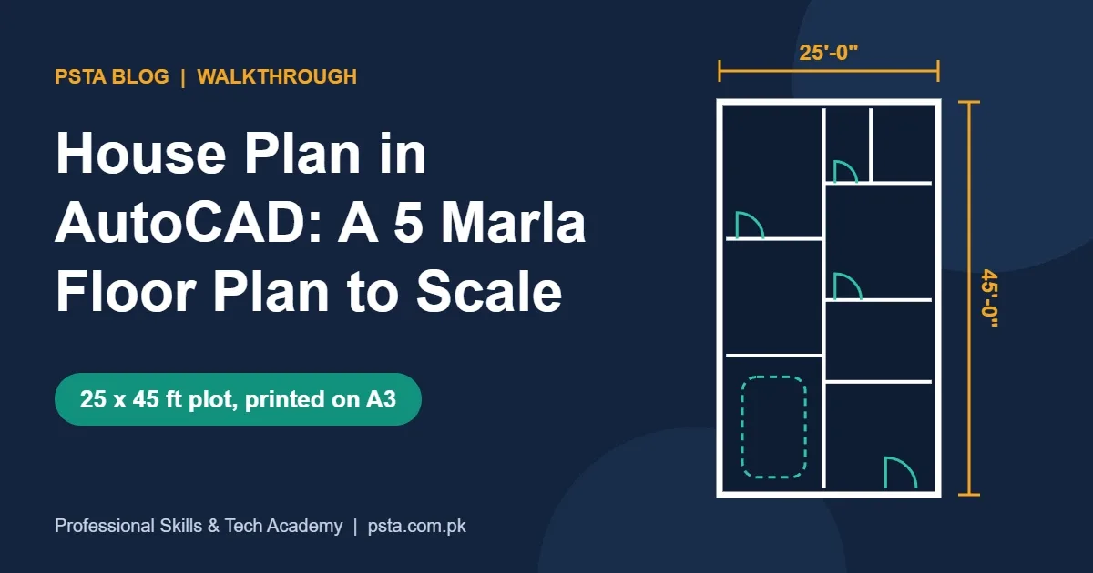
If you want more practice first, draw the 5 Marla plan from our house plan in AutoCAD walkthrough and plot it with the steps above. Our AutoCAD shortcut keys list will speed up the drafting part, and students can check eligibility for Autodesk's education license in the AutoCAD free for students checklist. If electrical panel layouts are your goal, the industrial automation course pairs well with drafting skills.
Measure Your Last PDF Today
Open the last PDF you plotted from AutoCAD and measure one dimension you know. If it matches the scale on your title block, you already have a working setup, so save it as a page setup and reuse it. If it doesn't, follow the nine steps on that same drawing tonight. For guided lessons, see how enrollment works on the admission page, or ask the PSTA office about batch timings through WhatsApp at +92 314 5424399.
Frequently asked questions
Why does my AutoCAD drawing not print to scale?
The usual cause is Fit to Paper, which picks whatever ratio fills the sheet. Other causes are drawing in meters while using millimeter scales, a viewport that was zoomed after scaling, or a print shop shrinking the PDF to fit printer margins. Plot the layout at 1:1, set an exact viewport scale, lock it and print at actual size.
What scale should I use for a house floor plan on A3?
For most houses, 1:100 is a sensible starting point on A3. A 12 m by 20 m footprint prints 120 by 200 mm, leaving room for a title block and notes. If you need more detail, use 1:50 on A2. For feet-and-inch drawings, 1/8 inch to a foot equals 1:96.
Should I plot from model space or a layout?
Use a layout for any drawing someone will measure, sign or submit. The layout plots at 1:1 because it represents the paper, and each viewport inside it carries its own scale. Model space plotting is fine for a quick check print of a single view, but title blocks and multiple scales become awkward.
How do I set a viewport to 1:100 in AutoCAD?
Select the viewport border and choose 1:100 from the Viewport Scale list on the status bar, or use the Properties palette. You can also double-click inside the viewport, type ZOOM and enter 1/100XP. Afterward, lock the viewport so scrolling the mouse wheel cannot change the scale by accident.
What is the difference between a CTB and an STB file?
A CTB file is color-dependent: each of its 256 styles is linked to an index color, so every red object prints the same way. An STB file holds named styles you assign to layers or objects, so two objects of the same color can print differently. Most students and small offices start with a CTB.
Why do my dashed lines print as solid lines?
The linetype scale does not suit the viewport scale. Check that PSLTSCALE is set to 1 so dashes follow paper space units, adjust LTSCALE if dashes are still too long or short, then type REGENALL. Existing viewports do not refresh until you regenerate them, so the fix can look like it failed.
How do I combine several layouts into one PDF?
Use EXPORTPDF to send every layout in the current drawing to one PDF file. If you need only some layouts, or sheets from more than one DWG file, use PUBLISH and pick the sheets you want. Each layout keeps its own saved page setup, so set those up correctly first.
Sources & references
- About Setting the Plot Scale (Autodesk) help.autodesk.com
- About Scaling Views in Layout Viewports (Autodesk) help.autodesk.com
- About Plot Style Tables (Autodesk) help.autodesk.com
- About Exporting Drawing Files to PDF (Autodesk) help.autodesk.com
- Page Setup Dialog Box (Autodesk) help.autodesk.com
- PSLTSCALE System Variable (Autodesk) help.autodesk.com
- Plotting True Color Objects in Monochrome (Autodesk Support) autodesk.com
- International Standard Paper Sizes (Markus Kuhn) cl.cam.ac.uk
Last reviewed & updated on by Umar Qureshi. Written by the PSTA team in Abbottabad, Pakistan.

Umar Qureshi

AutoCAD Mastery: 2D, 3D Design & BIM (Complete Professional Course)
Turn this guide into a career: hands-on training with real projects, online across Pakistan or on-campus in Abbottabad · 45 - 90 Days.


Comments
No comments yet — ask a question or share your experience.