Quick answer
IEC 61131-3 defines Ladder Diagram, Function Block Diagram, Structured Text and Sequential Function Chart, while Instruction List was deprecated in 2013 and dropped in 2025. Use ladder for interlocks, FBD for analog flow, ST for math and SFC for sequences. Learn ladder first, then add the others in that order.
Key takeaways
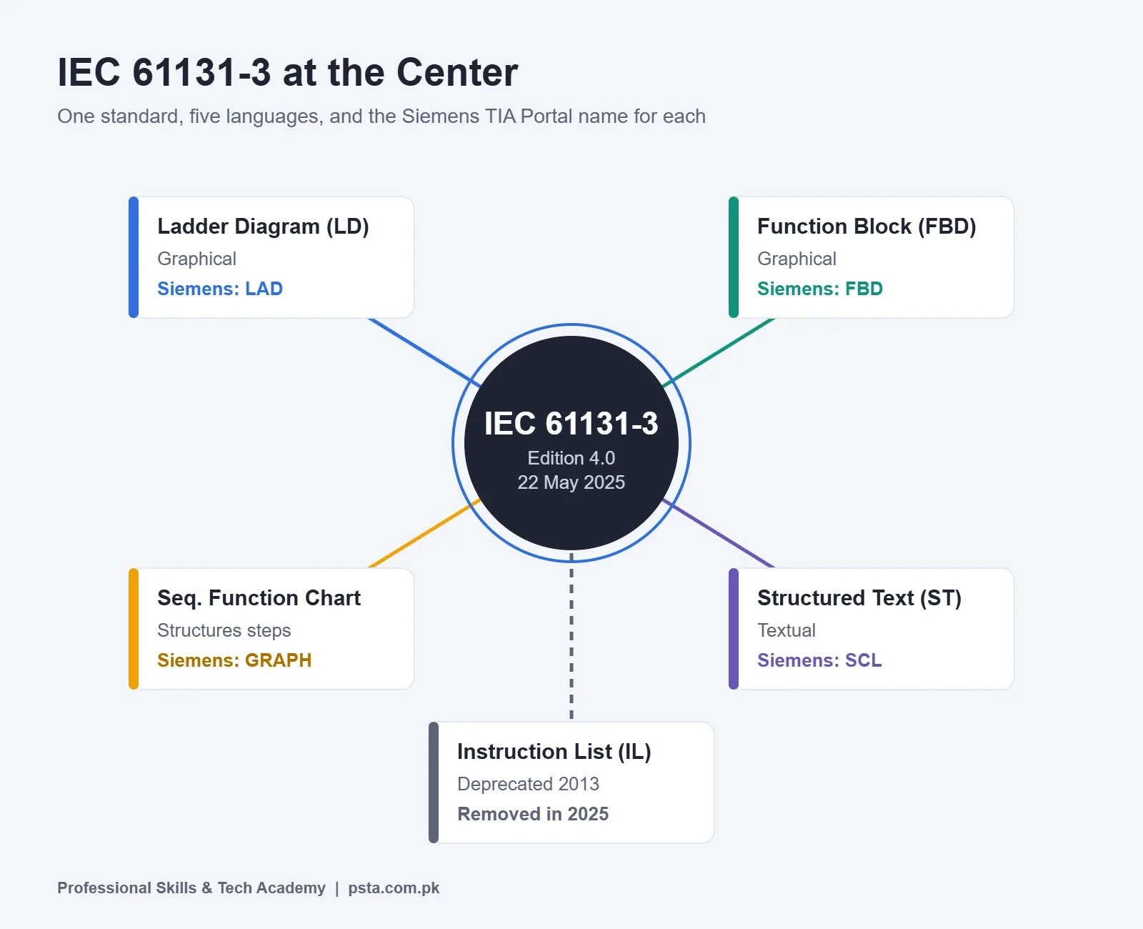
- • IEC 61131-3 edition 4.0, published 22 May 2025, defines Structured Text, Ladder Diagram, Function Block Diagram and Sequential Function Chart.
- • Instruction List was deprecated in the 2013 edition and removed in 2025, so read it for old machines but avoid it in new projects.
- • Siemens TIA Portal calls the languages LAD, FBD, SCL, GRAPH and STL; Rockwell Studio 5000 offers ladder, FBD, SFC and ST editors.
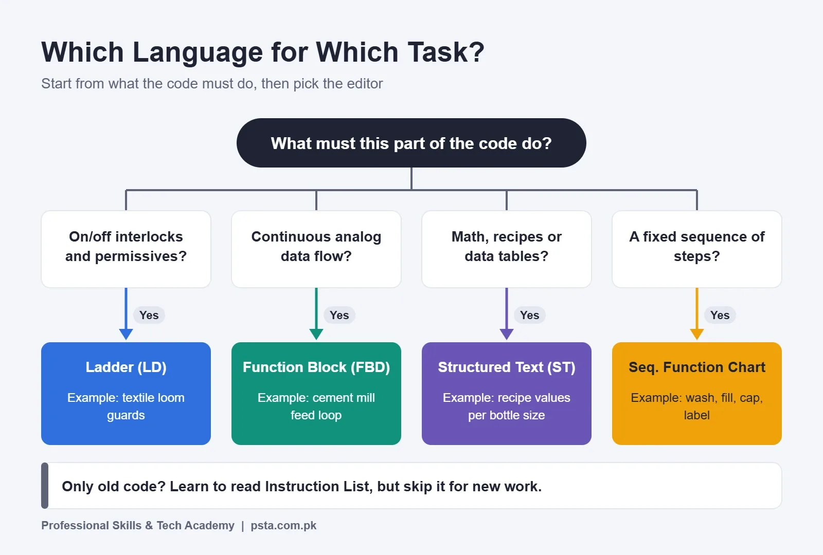
- • Choose by task: ladder for interlocks, FBD for analog data flow, ST for calculations and recipes, SFC for step sequences.
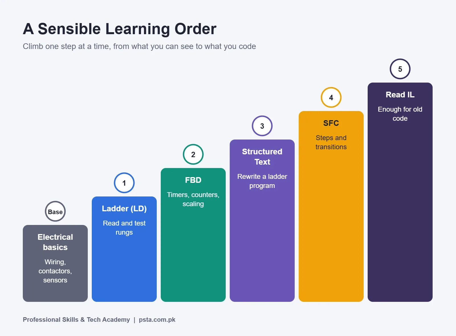
- • A practical learning order is electrical basics, then ladder, FBD, ST, SFC, and finally enough IL to read legacy code.
Table of contents 16 sections
- What Does IEC 61131-3 Actually Cover?
- Ladder Diagram (LD): Logic Drawn Like a Control Circuit
- Function Block Diagram (FBD): Wiring Blocks Together
- Structured Text (ST): When Logic Needs Real Code
- Sequential Function Chart (SFC): Steps and Transitions
- What Happened to Instruction List?
- How Brands Name PLC Programming Languages in Their Software
- Which Language Fits Which Factory Task?
- A Textile Spinning or Weaving Line
- A Cement Kiln or Mill Section
- A Food or Beverage Filling Line
- Mistakes to Avoid When Choosing
- Which PLC Programming Language Should You Learn First?
- Glossary of PLC Programming Terms
- How PSTA's Industrial Automation Course Builds Toward PLCs
- Start With One Small Translation
Here is an example: a maintenance technician at a hypothetical textile mill opens a PLC project and finds that it uses three different PLC programming languages at once. The rungs make sense to him, but the text routine and the step chart do not. This guide explains each language defined by IEC 61131-3, what it looks like, and where it fits on a real factory floor, so a project like that stops feeling foreign.
- A plain map of the five languages and how they relate to one standard.
- Short code samples so you can see each style for yourself.
- What Siemens, Rockwell, Mitsubishi and Delta call each language in their software.
- A simple way to match a language to a machine task.
- A suggested learning order and a glossary you can come back to.
What Does IEC 61131-3 Actually Cover?
IEC 61131-3 is the international standard for how programmable controllers are programmed. It is part 3 of the IEC 61131 series, the part that covers programming languages. Think of it as a shared rulebook that PLC makers can follow.
The IEC webstore listing for IEC 61131-3 gives the publication date of edition 4.0 as 22 May 2025. It names Structured Text as the textual language. It names Ladder Diagram and Function Block Diagram as the graphical ones. It adds Sequential Function Chart as a way to structure programs and function blocks. The listing also mentions an Annex B that records what was added, removed or deprecated since the 2013 edition.
Older editions had a fifth language. The PLCopen overview of IEC 61131-3 describes two textual languages, Instruction List and Structured Text, plus two graphical languages, Ladder Diagram and Function Block Diagram. It treats SFC as an extra set of elements with both a graphical and a textual form.
Why should you care about a standard? Because it gives the PLC programming languages of every brand a shared vocabulary. Once you know the IEC names, a Siemens screen and a Rockwell screen look far less different than their menus suggest.
Ladder Diagram (LD): Logic Drawn Like a Control Circuit
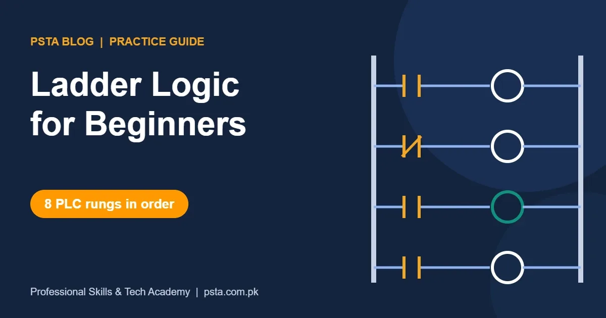
Of all the PLC programming languages, Ladder Diagram looks most like the relay drawings electricians already know. Two vertical rails run down the sides of the screen. Horizontal rungs connect them. Each rung holds contacts on the left and a coil or instruction on the right. If the contacts form a closed path, the output turns on.
Ladder is strong for on and off logic: start and stop circuits, interlocks, alarms and permissives. A technician can watch power flow across a rung while the machine runs, which makes fault finding fast.
We already have a full walkthrough of rungs, contacts and seal-in circuits in our post on ladder logic for beginners. This article stays at the comparison level, so read that one when you want to practice ladder itself.
Function Block Diagram (FBD): Wiring Blocks Together
Function Block Diagram replaces rungs with boxes. Each box is a function or function block, such as an AND gate, a timer, a comparator or a PID controller. Inputs enter on the left side of a box. Outputs leave on the right. You connect boxes with lines, much like signal wiring on a drawing.
FBD feels natural when data flows from one stage to the next. A temperature reading goes into a scaling block, then into a comparison block, then into an alarm. Process engineers often like it because it resembles the loop diagrams they use for instruments.
The main risk with FBD is clutter. A large sheet with crossing lines gets hard to follow. Good practice is to keep each network small and to wrap repeated logic into your own function blocks.
Structured Text (ST): When Logic Needs Real Code
Structured Text is the high-level textual option among PLC programming languages. If you have seen any general programming language, it will look familiar. It has IF statements, CASE statements, loops and math expressions. Here is a small tank fill routine written in a typical ST style:
IF Level < LowSetpoint THEN
    FillValve := TRUE;
ELSIF Level >= HighSetpoint THEN
    FillValve := FALSE;
END_IF;

FlowRate := (Level - LastLevel) / ScanTime;
ST shines when you need calculations, data handling or recipe tables. Doing the same math in ladder takes many rungs of compute instructions. In ST it is often one line.
The tradeoff is visibility. A maintenance person cannot see power flow in text. That is why many plants keep machine interlocks in ladder and put the heavy math in ST.
Sequential Function Chart (SFC): Steps and Transitions
Sequential Function Chart organizes a process as a series of steps. Each step has actions. Between steps sit transitions, which are conditions that must become true before the chart moves on. The chart reads top to bottom, like a flowchart.
Take a hypothetical batch mixer as an example. Step 1 opens the inlet valve. The transition waits for the high level switch. Step 2 runs the agitator. The transition waits for a timer to finish. Step 3 opens the drain. When the low level switch turns on, the chart returns to the start.
Compared with the other PLC programming languages, the special value of SFC is that you can see which step the machine is in right now. When a sequence stalls, you look for the active step and check its transition. The actions inside each step are usually written in another language, such as ladder or ST.
What Happened to Instruction List?
Instruction List is the assembly-style text option among PLC programming languages. It works at a very low level. Each line holds one operator and one operand. A start and stop circuit might look like this:
LD   Start
OR   Motor
ANDN Stop
ST   Motor
The Wikipedia entry on IEC 61131-3 notes that Part 3 was first published in December 1993. It also states that IL was deprecated in the third edition of 2013 and removed in the fourth edition of 2025. An article from Motion Control Tips on why IL is falling out of favor cites the IEC technical report TR 61131-8 and explains that an assembler-style language no longer suits modern tools.
You will still meet IL, or a vendor version of it, in older machines. So learn to read it. Just do not choose it for new work.
How Brands Name PLC Programming Languages in Their Software
Each vendor uses its own labels for PLC programming languages, and this is where many beginners get confused. The table below maps the IEC names to the names you will see in each tool, based on the official pages listed under it.
| IEC 61131-3 name | Siemens TIA Portal (STEP 7) | Rockwell Studio 5000 Logix Designer | Delta ISPSoft |
|---|---|---|---|
| Ladder Diagram (LD) | LAD | Ladder diagram | LD |
| Function Block Diagram (FBD) | FBD | Function block diagram | FBD |
| Structured Text (ST) | SCL | Structured text | ST |
| Sequential Function Chart (SFC) | GRAPH | Sequential function chart | SFC |
| Instruction List (IL) | STL | Not listed | IL |
The Siemens column comes from the Siemens function manual on IEC 61131-3 compliance for STEP 7 in TIA Portal. That manual maps LAD to LD, FBD to FBD, SCL to ST, GRAPH to SFC and STL to IL. So when a Siemens engineer says "SCL", you can read it as Structured Text.
The Rockwell Studio 5000 Logix Designer documentation lists editors for ladder diagram, function block diagram, sequential function chart and structured text. The Delta ISPSoft product page says it supports all five, LD, FBD, SFC, IL and ST, for the DVP, AS and AH series.
Mitsubishi is a little different. The Mitsubishi GX Works3 product page mentions ladder and ST, says the software complies with IEC 61131-3, and names the MELSEC iQ-R and iQ-F series. Check the GX Works3 manual for the exact language list on your model before you plan a project.
Which Language Fits Which Factory Task?
No single one of the PLC programming languages wins everywhere. The better question is what the code has to do. Here are three hypothetical examples from the kinds of plants you find across Pakistan.
A Textile Spinning or Weaving Line
Picture a hypothetical ring frame or loom section with many motors, guards and stop buttons. Most of the logic is interlocks and safety permissives. Ladder fits well here. A shift electrician can open the rung, see which contact is open and fix the problem quickly.
A Cement Kiln or Mill Section
In a hypothetical cement plant, a mill feed loop reads analog signals, scales them and drives a VFD speed reference. That is continuous data flow, so FBD often suits it. If the plant also needs ratio calculations or report data, ST handles that part neatly. For background on the drives side, see our comparison of VFD vs soft starter.
A Food or Beverage Filling Line
Take a hypothetical juice line with wash, fill, cap and label stages. The machine moves through fixed steps, and operators need to know which step it is on. SFC organizes the sequence, ladder handles the motor interlocks, and ST can store recipe values for each bottle size.
Mixing languages inside one project is common, and the vendor tools in the table above each offer several editors. Pick the language that makes each part easiest for the next person to read.
Mistakes to Avoid When Choosing
A common mistake is writing everything in whichever of the PLC programming languages you like best. If you love code, you may put motor interlocks in ST. Then the night shift cannot see why a conveyor will not start. Keep visible logic in a visible language.
Another mistake is assuming every controller supports every language. Small or older models may not. As the brand table shows, vendors differ, so confirm with the official manual for your exact CPU.
A third one is ignoring naming. Clear tag names and comments help more than any language choice. A neat ladder program with good names beats a clever ST routine that nobody can follow.
Which PLC Programming Language Should You Learn First?
For most beginners in Pakistan, the order below works well. It starts with what you can see and test, then moves to code that needs more abstract thinking.
- Start with ladder. It builds on motor control circuits and is the language you will read most during maintenance work.
- Add function block diagram. Learn timers, counters and comparators as blocks. Then try one analog scaling example.
- Move to structured text. Rewrite one of your ladder programs in ST. Then add a small calculation that would be awkward in ladder.
- Learn sequential function chart. Break a machine you know, such as a car wash or a mixer, into steps and transitions.
- Learn to read instruction list. You only need enough to understand old code during a retrofit. Do not spend weeks on it.
Before step 1, make sure your electrical basics are solid. Wiring, contactors, overloads and sensors come first, because every PLC program ends at a real terminal. If you want to prepare for job interviews later, our list of PLC interview questions shows what employers tend to ask.
Glossary of PLC Programming Terms
These short definitions cover words you will meet in any of the PLC programming languages above. Keep this list open while you read your first projects.
- Scan cycle: The repeating loop a PLC runs. It reads inputs, runs the program, then writes outputs.
- Tag or variable: A named memory location, such as Start_PB or Tank_Level, that holds a value.
- Data type: The kind of value a tag holds. BOOL is on or off, INT is a whole number, REAL is a decimal number.
- Rung: One horizontal line of logic in a ladder program.
- Contact: A ladder symbol that checks the state of a bit. Normally open passes power when the bit is on.
- Coil: A ladder output symbol that sets a bit on when its rung is true.
- Function: A block that gives the same output for the same inputs every time and keeps no memory, such as ADD.
- Function block: A block with its own memory, such as a timer or counter. Each use needs its own instance.
- Instance: One copy of a function block with its own data. Two timers mean two instances.
- POU (Program Organization Unit): The IEC term for a program, function or function block.
- Step: A state in an SFC chart. Actions run while the step is active.
- Transition: The condition that moves an SFC chart from one step to the next.
- Task: A setting that decides when a program runs, for example every cycle or every 100 ms.
- Deprecated: Still allowed for now but discouraged, with removal expected in a later edition.
How PSTA's Industrial Automation Course Builds Toward PLCs
At PSTA, the Industrial Automation course runs for 3 months (12 weeks) at beginner level. The fee is Rs. 28,000, down from a regular Rs. 35,000. It is aimed at DAE and B-Tech graduates and working electricians.
The course follows the order this article recommends. You start with industrial electricity and safety, then control components and protection. Next come hardwired motor control circuits, sensors and input devices, and motor drives with soft starters. Module 6 introduces PLC and HMI integration. After that you practice industrial fault finding and finish with a final project and certification. Your instructor is Umar Qureshi, and certificates can be checked on the certificate verification page.
If you also want to draw panel layouts and wiring sheets, the AutoCAD course pairs well with automation work. Other technical programs are listed on the all courses page.
Start With One Small Translation
Here is one practical action. Take a simple start and stop circuit you already understand. Draw it as a ladder rung on paper. Then write the same logic as one line of structured text, and sketch it as two FBD blocks. Seeing one idea in three PLC programming languages teaches you more than reading about all five.
When you feel ready for guided practice, you can join classes at our Abbottabad campus, attend live from anywhere in Pakistan, or combine both. Batches open monthly, and the admission page explains how to enroll. For timings or questions, send us a message on WhatsApp and we will reply with the current schedule.
Frequently asked questions
How many PLC programming languages does IEC 61131-3 define today?
The current fourth edition, published in May 2025, covers four: Ladder Diagram, Function Block Diagram, Structured Text and Sequential Function Chart. Older editions also included Instruction List. You will still see IL in older projects and in some vendor tools, so it helps to recognize it even though new standard-based work no longer relies on it.
Is SCL in Siemens the same as Structured Text?
Yes, in practice. The Siemens compliance manual for STEP 7 in TIA Portal maps SCL to the IEC Structured Text language. Siemens adds its own instructions and editor features, so code does not always copy across brands without edits, but the core syntax of IF, CASE, loops and assignments follows the same pattern you would learn for ST.
Can I mix ladder and structured text in one PLC project?
Usually yes. Most modern tools let you create separate routines or blocks in different editors and call them from each other. A common layout keeps interlocks in ladder for maintenance staff and places calculations in ST. Check your controller model first, since small or older CPUs may limit which editors are available.
Do I need to learn Instruction List at all?
Only enough to read it. Many older machines still run IL or a vendor version such as Siemens STL, so a retrofit or a fault call may put that code in front of you. Spend a few practice sessions learning the basic load, AND, OR and store operators, then put your main effort into the current languages.
Which language do maintenance technicians use most?
On most shop floors, ladder is the one technicians open first, because it shows live power flow and matches the relay drawings they already know. That makes it quick to find which contact is blocking an output. Engineers who build new systems tend to use FBD, ST and SFC more, often alongside ladder in the same project.
Is GRAPH in TIA Portal the same thing as SFC?
Siemens maps its GRAPH language to the IEC Sequential Function Chart in its compliance documentation. Both organize a process into steps, actions and transitions. If you understand SFC concepts from one brand, such as Rockwell's SFC editor, you can transfer that thinking to GRAPH quite easily, though the menus and some details differ.
Do I need a programming background to learn structured text?
No. It helps, but plenty of electricians learn ST after ladder. Start by rewriting small ladder programs as text, such as a motor start and stop or a tank fill. Once IF statements and assignments feel natural, add calculations. Having a working ladder version to compare against makes mistakes easier to spot.
Sources & references
- IEC 61131-3:2025 Programmable controllers - Part 3: Programming languages webstore.iec.ch
- PLCopen: IEC 61131-3 and PLCopen plcopen.org
- Siemens: Standards compliance according to IEC 61131-3 (3rd Edition), STEP 7 in TIA Portal cache.industry.siemens.com
- Rockwell Automation: Studio 5000 Logix Designer documentation rockwellautomation.com
- Delta Electronics: ISPSoft programming software delta-emea.com
- Mitsubishi Electric: GX Works3 us.mitsubishielectric.com
- Wikipedia: IEC 61131-3 en.wikipedia.org
- Motion Control Tips: Why is the instruction list (IL) language for PLCs falling out of favor? motioncontroltips.com
Last reviewed & updated on by Umar Qureshi. Written by the PSTA team in Abbottabad, Pakistan.

Umar Qureshi

Master Industrial Automation: Single & Three-Phase Panel Wiring, PLC & VFD Certification
Turn this guide into a career: hands-on training with real projects, online across Pakistan or on-campus in Abbottabad · 3 Months (12 Weeks).

Comments
No comments yet — ask a question or share your experience.