Quick answer
A PNP sensor sources current: its black output switches to +V and needs a sinking PLC input with the common on 0 V. An NPN sensor sinks current: its output switches to 0 V and needs a sourcing input with the common on +24 V. Wire colors are identical, so check the part number or test it.
Key takeaways
- • PNP outputs switch +V and need a sinking input; NPN outputs switch 0 V and need a sourcing input.
- • Brown, blue and black mean +V, 0 V and output on both types, so colors can't reveal the output type.
- • A lamp between black and 0 V that lights on detection marks a PNP sensor; between +24 V and black, an NPN sensor.
- • If a chafed output wire touches 0 V, an NPN input reads ON while a PNP input reads OFF.
- • When types don't match, fit the right sensor first; a group common change, converter or interposing relay are fallbacks.
Table of contents 16 sections
- PNP vs NPN Sensor: The Difference in One Minute
- What Do Sinking and Sourcing Actually Mean?
- Side-by-Side Comparison Table
- Proximity Sensor Wire Colors: What Each Wire Does
- Which PLC Input Does Each Sensor Need?
- How Do You Tell PNP From NPN With a Multimeter?
- Which Is Safer When a Cable Gets Damaged?
- Why Do Asian Machines Often Use NPN?
- What If the Sensor and PLC Don't Match?
- 1. Fit the Correct Sensor
- 2. Change the Input Common
- 3. Use a PNP/NPN Converter
- 4. Add an Interposing Relay
- Wiring Checks Before You Power Up
- Practising Sensor Wiring in PSTA's Industrial Automation Course
- Before Your Next Panel Job: Tag Every Sensor
The sensor's LED glows every time a metal bracket passes, yet the PLC input never turns on. On a new panel, that symptom usually points to one thing: the PNP vs NPN sensor choice doesn't match how the PLC input is wired. A PNP sensor switches +24 V onto its output wire. An NPN sensor switches the output wire to 0 V. The PLC input has to be built, or set, for one of those two signals.
This comparison is written for electricians, DAE students and junior maintenance technicians who wire panels and want to stop guessing. Here is what you will take away:
- What PNP, NPN, sourcing and sinking mean in plain wiring terms
- The wire colors on a 3-wire and 4-wire DC sensor, and what each one does
- Which PLC input type each sensor needs, with a simple matching chart
- A test-lamp method to identify an unlabeled sensor on the bench
- Four practical fixes when the sensor and the PLC don't match
PNP vs NPN Sensor: The Difference in One Minute
Inside every 3-wire DC proximity or photoelectric sensor is a small transistor that acts as the switch. The letters PNP and NPN name the type of transistor. For wiring, though, you only need to remember what the output wire does when the sensor detects a target.
- PNP (sourcing): the black output wire connects to +V. The load sits between the output and 0 V.
- NPN (sinking): the black output wire connects to 0 V. The load sits between +V and the output.
The sensor maker autosen describes it the same way: with a PNP output, 0 V is the reference for the load, and with an NPN output, +V is the reference. When nothing is detected, a normally open output of either type simply floats, so a meter on that wire alone tells you very little. Keep that in mind; we'll come back to it in the testing section.
One more detail trips people up. As Arrow Electronics points out, the transistor's internal base voltage is never something you see from the panel side, which is why the names feel backwards to many beginners. Don't try to reason from the transistor symbol. Reason from the output wire.
What Do Sinking and Sourcing Actually Mean?
These two words describe the direction of current at a terminal, and they apply to DC circuits only. AutomationDirect's guide to 3-wire devices and PLC inputs puts it simply: a sinking terminal provides the path to supply common (0 V), and a sourcing terminal provides the path to supply source (+V).
Apply that to both ends of the cable:
- A PNP sensor sources current into the PLC input. So the input must sink it to 0 V.
- An NPN sensor sinks current from the PLC input. So the input must source it from +24 V.
Current needs one side pushing and one side receiving. Two sourcing ends push against each other, and two sinking ends both wait for current that never arrives. In both cases the input stays off.
A word of caution from the classroom: PLC brands don't all use these words the same way in their manuals. Some name an input mode after the sensor it accepts rather than the direction of current at the terminal. When the label and the logic disagree, trust the wiring diagram in that PLC's own manual.
Side-by-Side Comparison Table
Use this PNP vs NPN sensor table when you're reading a datasheet or a panel drawing. The specification row uses the Autonics PRD cylindrical series as a real example, because its brochure lists both output types with identical ratings.
| Point | PNP Sensor | NPN Sensor |
|---|---|---|
| Other name | Sourcing output | Sinking output |
| Output wire when ON | Close to +V | Close to 0 V |
| Load connected between | Black and blue (0 V) | Brown (+V) and black |
| PLC input it needs | Sinking input (common to 0 V) | Sourcing input (common to +24 V) |
| Autonics code, normally open | DP | DN |
| Autonics code, normally closed | DP2 | DN2 |
| Autonics PRD rating (both types) | 12-24 VDC, max 200 mA | 12-24 VDC, max 200 mA |
| Where it's typical | Most European machines | Still found on many Asian-built machines |
| Cable chafes and output touches 0 V | Input reads OFF | Input reads ON |
Notice that ratings, sensing distance and housing are the same. The only thing that changes is the output stage, so you can't pick one by size or price alone. You have to pick it by the input it will feed.
Proximity Sensor Wire Colors: What Each Wire Does
DC sensors follow a color code from EN 60947-5-2, the sensor standard. Pepperl+Fuchs lists it like this:
- Brown (BN): positive supply, +V
- Blue (BU): negative supply, 0 V
- Black (BK): switching output, normally open in a 3-wire sensor
- White (WH): on a 4-wire sensor, the second output, normally closed
PNP sensor wiring and NPN sensor wiring use the same colors. That's exactly why a technician can wire the brown and blue correctly, see the LED respond, and still get no signal at the PLC. The colors tell you which wire is which. They don't tell you the output type. For that you need the model code, the label or a quick bench test.
In Pakistan, both versions sit side by side in local stock. A Pakistani online automation supplier, for example, lists the Autonics PRD12-4DP, where the DP at the end marks a PNP normally open output. Read the last letters of the part number before you pay, not after the sensor is mounted.
Which PLC Input Does Each Sensor Need?
Most PLC input wiring faults with sensors come down to this pairing. There are only four combinations, and two of them work. That's the whole idea behind the PNP vs NPN sensor question.
- PNP sensor into a sinking input: works. Current flows from the sensor into the input, through the input circuit and out of the common to 0 V.
- NPN sensor into a sourcing input: works. Current flows from +24 V at the input common, out of the input terminal and down through the sensor to 0 V.
- PNP into a sourcing input: no current path. The input stays off.
- NPN into a sinking input: no current path. The input stays off.

Many compact PLCs let you choose. Their DC inputs share a common terminal, and the voltage you put on that common decides the mode. Connect the common to 0 V and the group becomes sinking, ready for PNP sensors. Connect it to +24 V and the group becomes sourcing, ready for NPN sensors. Delta's DVP manuals label this terminal S/S. AutomationDirect adds an important rule for these sink/source modules: all points on one common work the same way, so you can't mix PNP and NPN sensors on the same group.
How Do You Tell PNP From NPN With a Multimeter?
NPN sensor wiring looks identical to PNP on the outside. Old machines often carry sensors with worn labels, so the PNP vs NPN sensor question has to be settled on the bench. You can still identify them in a couple of minutes. A meter alone can mislead you, because an open-collector output floats when it has no load. So give the output a load first. A 24 V pilot lamp is ideal, and so is a small 24 V relay.
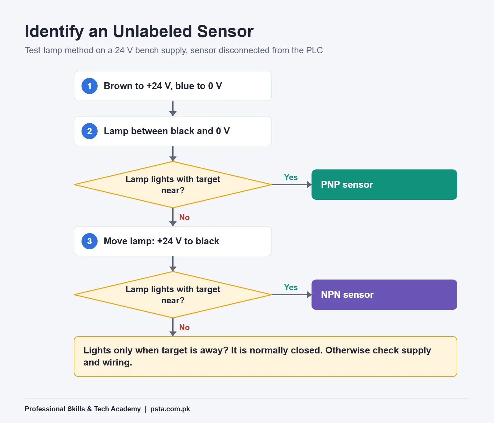
- Disconnect the sensor from the PLC. Keep the machine isolated if you're working on site.
- Connect brown to +24 V and blue to 0 V from a bench supply.
- Connect the test lamp between the black wire and 0 V (blue).
- Bring a metal target near the sensor face. If the lamp lights, the sensor is PNP. Stop here.
- If the lamp stays dark, move it so it sits between +24 V (brown) and the black wire.
- Present the target again. If the lamp lights now, the sensor is NPN.
- If the lamp lights only when the target is away, you have a normally closed sensor. Note that too.
- Write the result on a cable marker or tag before you reconnect anything.
With the lamp still connected, a multimeter confirms the reading. Measure the black wire against blue. A PNP output that's ON reads close to the supply voltage. An NPN output that's ON reads close to 0 V. It won't be exactly the supply or exactly zero: Autonics specifies a residual voltage of up to 1.5 V for its 12 mm, 18 mm and 30 mm PRD sensors, and up to 2 V for the 8 mm size.
Which Is Safer When a Cable Gets Damaged?
Sensor cables live a hard life. They get pinched in cable trays, rubbed by moving guards and splashed with coolant. Think about what happens when the black output wire's insulation wears through and the copper touches the grounded machine frame, which sits at 0 V in most panels.
With an NPN sensor, the output already means ON when it's pulled to 0 V. A short to the frame looks exactly like a detected target. Arrow's article describes this case directly: a frayed NPN output that grounds reads as an ON signal, which can be a hazard. A conveyor might start, or a step in a sequence might be skipped.
With a PNP sensor, the same short pulls the input to 0 V, so the PLC reads OFF. A missing signal usually stops a machine instead of starting one. This is one reason, alongside the easier logic of "positive means on," that PNP is the common choice in industrial sensing. Never treat either type as a safety device, though. Real guarding and emergency stops need properly rated safety components.
Why Do Asian Machines Often Use NPN?
If you work in a textile mill, a food plant or a packaging line, you'll see machines from many countries on the same floor. The output type often follows where the machine was built. Autosen notes that most European machines run on PNP sensors, while NPN is still used to some extent in Asia. Arrow says something similar: NPN sensors are more common in Asian manufacturing than in Europe and North America.
For a maintenance technician in Hattar or Gadoon, that has a practical meaning. Before you order a replacement, check the sensor that came out of the machine, or the machine's I/O drawing. Don't assume the PNP version because it's what the last machine used. Ordering the wrong output type costs you a second trip to the supplier and hours of downtime.
What If the Sensor and PLC Don't Match?
Sometimes the spare on the shelf is the wrong type and production is waiting. You have four honest options, listed from best to least preferred.
1. Fit the Correct Sensor
This is the cleanest fix. Same housing, same sensing distance, matching output. With Autonics, that often means swapping a DN model for the DP model, or the reverse.
2. Change the Input Common
If the PLC has a configurable common and every sensor on that group can change together, rewire the common. This only works when you're changing the whole group. One odd sensor on a group of PNP devices can't be fixed this way.
3. Use a PNP/NPN Converter
Some manufacturers sell converter cables or modules that flip the output type. Autosen, for instance, lists converter cables for normally open and normally closed PNP sensors. Check the converter's ratings against your sensor and input before fitting it.
4. Add an Interposing Relay
Wire the sensor to drive a 24 V DC relay coil the correct way for its output type. Then feed the PLC input through the relay's dry contact. It's slower and adds a part, so don't use it for fast counting. For a slow position check, it's a dependable temporary fix.
A pull-up or pull-down resistor can also make a mismatched pair work, but the resistor value depends on the input's current draw. Leave that method until you've read the input specifications carefully.
Wiring Checks Before You Power Up
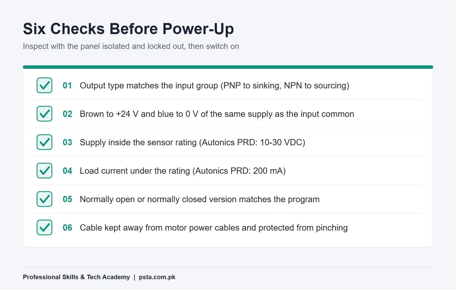
Most sensor faults on a new panel are wiring faults. Run through these checks before the first switch-on. Do the inspection with the panel isolated and locked out, and power up only after the checks pass.
- Sensor output type (PNP or NPN) matches the input group's wiring
- Brown goes to +24 V and blue goes to 0 V of the same DC supply that feeds the input common
- Sensor supply sits inside its rating; Autonics PRD models list an operating range of 10-30 VDC
- The load on the output stays under the sensor's rated current, such as 200 mA for the PRD series
- Normally open or normally closed version matches what the program expects
- Cable is routed away from motor power cables and protected where it can be pinched
One more check belongs to the PLC side. The input has to see enough voltage to switch. According to an Analog Devices design note on the IEC 61131-2 standard, Type 1 inputs read ON from about 15 V and Type 3 inputs from about 11 V, while anything under 5 V is OFF. A healthy 24 V supply clears those levels easily. A sagging supply or a long, thin cable can push a signal into the uncertain zone, which shows up as an input that flickers.
Also look at outputs, not just inputs. Control.com notes that sinking is the more common input style, and that most PLC output terminals are sourcing. A sourcing output supplies 24 V when it turns on, which is why its loads return to 0 V.
Practising Sensor Wiring in PSTA's Industrial Automation Course
Reading about PNP and NPN helps, but the idea becomes permanent after you've wired both types to a real input and watched one of them fail. PSTA's Industrial Automation: Panel Wiring, PLC & VFD course gives sensors their own module, Module 4: Sensors & Input Devices. It sits after motor control circuits and before VFDs, soft starters and the PLC and HMI module.
The program runs for 12 weeks and is pitched at beginners. Its listed fee is Rs. 28,000, so check the course page for the current figure before you enroll. You can join in person at the Abbottabad campus, attend the same classes live from another city, or mix the two, and a fresh batch opens each month. Most learners are DAE or B-Tech students, working electricians who want industrial work, and maintenance staff already inside a factory.
If you're new to PLCs, it helps to read our guide to ladder logic for beginners and the explainer on PLC programming languages first. Panel drawings will also make more sense after our walkthrough of electrical symbols for control panels. When you're ready, the admission page explains how to join, and you can compare other programs on the full course list. For fee or batch questions, message the PSTA team on WhatsApp at +92 314 5424399.
Before Your Next Panel Job: Tag Every Sensor
Pick one machine you look after. For each DC sensor on it, write down the part number, the output type and whether it's normally open or closed, then put a small tag on the cable. If a label is unreadable, use the test-lamp method above. It takes an afternoon, and the next time a sensor fails at 2 a.m., whoever is on shift will order the right replacement the first time.
Frequently asked questions
Can I connect a PNP sensor to a PLC input wired for NPN sensors?
Not directly. An input group wired for NPN sensors has its common on +24 V, so it is sourcing, and a PNP sensor also sources current. No current path forms and the input stays off. Rewire the common if every sensor on that group can change together, or fit a matching sensor. A converter cable or an interposing relay can work as a stopgap.
Which is better, a PNP or an NPN sensor?
Neither is better in every case. The right sensor is the one that matches the PLC input you already have. PNP is common on European machines and reads OFF if a damaged output wire touches 0 V, which many engineers prefer. NPN still appears on many Asian-built machines. When you replace a sensor, match the original output type unless you are rewiring the whole input group.
What do the brown, blue and black wires on a proximity sensor mean?
Under the EN 60947-5-2 color code, brown is the positive supply, blue is 0 V and black is the switching output. A 4-wire sensor adds white as a second output, usually normally closed. The colors are the same on PNP and NPN models, so they tell you which wire is which but not the output type. Check the part number or test the sensor.
What happens if I connect a sensor with the wrong output type?
In the usual mismatch, the sensor powers up and its LED still responds to targets, but no current flows through the PLC input, so the input never turns on. That makes the fault confusing at first. Confirm that brown and blue are on the correct supply terminals, then compare the sensor's output type with how the input common is wired.
How do I know if my PLC input is sinking or sourcing?
Look at what the input common terminal connects to. If the common goes to 0 V, the inputs are sinking and suit PNP sensors. If it goes to +24 V, they are sourcing and suit NPN sensors. Brands sometimes use these words differently, so always confirm with the wiring diagram in that PLC's manual before you change anything.
What do DP and DN mean in an Autonics sensor part number?
In Autonics PRD-series codes, DN means a DC NPN output that is normally open, and DP means a DC PNP output that is normally open. Adding a 2, as in DN2 or DP2, means the output is normally closed. Reading these last letters before you buy saves a return trip when a sensor must match an existing input group.
Is an NPN sensor dangerous?
An NPN sensor isn't dangerous by itself, but its failure mode needs thought. If a chafed output wire touches the grounded frame at 0 V, the PLC reads the input as ON, which could start or advance a machine. With PNP, the same fault reads OFF. Neither type replaces proper safety devices such as rated guards and emergency stops.
Sources & references
- Sinking and Sourcing: 3-Wire Devices and PLC Input Modules (AutomationDirect) library.automationdirect.com
- PNP or NPN? (autosen) autosen.com
- NPN vs. PNP: What's the Difference? (Arrow Electronics) arrow.com
- Sensor Wire Colors and Plug Assignment per EN 60947-5-2 (Pepperl+Fuchs) rockwell.pepperl-fuchs.com
- PRD/PRDA DC 3-Wire Proximity Sensor Brochure (Autonics) res.cloudinary.com
- Industrial Digital Inputs With the MAX22191 (Analog Devices) analog.com
- Sourcing vs. Sinking for Control System Modules Explained (Control.com) control.com
Last reviewed & updated on by Umar Qureshi. Written by the PSTA team in Abbottabad, Pakistan.

Umar Qureshi

Master Industrial Automation: Single & Three-Phase Panel Wiring, PLC & VFD Certification
Turn this guide into a career: hands-on training with real projects, online across Pakistan or on-campus in Abbottabad · 3 Months (12 Weeks).


Comments
No comments yet — ask a question or share your experience.