Quick answer
Use a relay for control signals and small loads, usually below 10 A. Use a contactor for motors, heaters and other power loads, because it has arc chutes, heavier poles and AC-3 motor ratings. Most motor panels use both, with a relay driving the contactor coil and the contactor switching the motor.
Key takeaways
- • Relays switch control signals and light loads, usually below 10 A and 250 V.
- • Contactors switch motors and heavy loads, with arc chutes and ratings up to 1,000 V.
- • Size a motor contactor by its AC-3 current or kW figure, never by the AC-1 figure.
- • In most panels a relay drives the contactor coil, and the contactor switches the motor.
- • Reversing starters need electrical and mechanical interlocks between the two contactors.
Table of contents 12 sections
- Contactor vs Relay: The Short Version
- What Does a Relay Do in a Control Panel?
- Where Relays Earn Their Place
- What Makes a Contactor Different?
- Reading a Contactor Label: AC-1, AC-3 and AC-4
- Which One Should You Use? A Four-Question Check
- How Do a Relay and a Contactor Share One Motor Circuit?
- Why Forward-Reverse Starters Depend on Contactor Interlocks
- Is an Overload Relay a Relay or a Contactor?
- Mistakes That Burn Out Contacts and Coils
- Practising Contactor and Relay Wiring at PSTA
- Before Your Next Panel Job: Read Two Labels
Example scenario that sums up the contactor vs relay question: a flour mill owner near Abbottabad asks a new electrician to switch a 4 kW three-phase motor from a small timer. The electrician reaches for a plug-in relay because it's cheap and already in his toolbox. The relay is rated 7 A at 250 V, has no arc chute and isn't built for a motor's starting current, so it pits and welds within weeks. The fix was never a "stronger relay." It was a contactor, driven by that same timer.
That small mix-up shows why the difference between contactor and relay matters. Both are switches worked by a coil, and on a parts counter they can look like cousins. In a panel, they do very different jobs. This comparison explains where each one belongs, using real datasheet numbers rather than rules of thumb.
Here is what this comparison covers:
- The practical differences in current, voltage, contacts and arc handling
- How to read AC-1, AC-3 and AC-4 on a contactor label
- A four-question check to choose the right device for a load
- How a relay and a contactor share one motor starter circuit
- Where the overload relay fits, and why its name confuses trainees
Contactor vs Relay: The Short Version
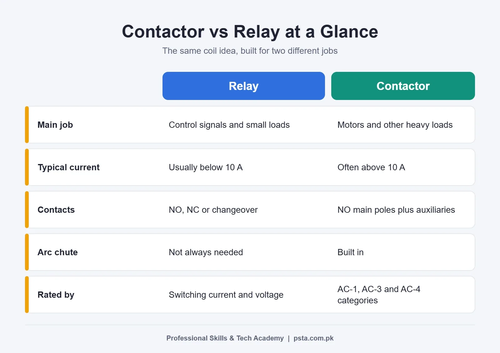
The contactor vs relay difference fits in one line each. A relay is a small coil-operated switch for control signals and light loads. A contactor is a heavier coil-operated switch built to make and break power circuits, especially motors, many times a day. The coil principle is the same. The size of the contacts, the arc handling and the ratings are not.
Schneider Electric's own relay and contactor explainer puts the dividing line at roughly 10 A: relays are usually below it, contactors are often above it. A Control.com technical article gives a similar picture, with typical relays under 10 A, under 0.5 HP and generally under 250 V, while contactors go up to 1,000 V.
| Point | Relay | Contactor |
|---|---|---|
| Main job | Switch control signals and small loads | Switch power to motors, heaters and other heavy loads |
| Typical current | Usually below 10 A | Often above 10 A, up to hundreds of amps |
| Typical voltage | Control relays generally under 250 V | Main poles rated up to 1,000 V |
| Contacts | NO, NC or changeover (CO) | Main poles are normally open, plus auxiliary NO/NC contacts |
| Arc handling | Not always needed | Built-in arc chutes |
| Mounting | Plug-in socket or PCB | DIN rail or panel plate, screw terminals |
| Rating language | Switching current and voltage | Utilization categories such as AC-1 and AC-3 |
| Typical place in a panel | Control circuit, PLC outputs, alarms | Power circuit, motor starters |
What Does a Relay Do in a Control Panel?
Think of a relay as a translator between circuits. A small signal, such as a 24 V DC PLC output or a float switch, energizes the coil. The coil pulls a set of contacts, and those contacts switch a separate circuit that the signal source couldn't safely drive on its own.
A good example is the Finder 55 series general-purpose relay. The RS listing for a Finder 55.34 relay shows a 230 V AC coil, four changeover contacts, 7 A switching current and 250 V AC maximum switching voltage, mounted in a plug-in socket. That's a lot of contacts for a small body. It's also why relays shine in logic work.
Where Relays Earn Their Place
- Interfacing: letting a PLC, timer or sensor control a 230 V circuit while keeping the two electrically separate.
- Multiplying signals: one input, four outputs, for example a fault lamp, a buzzer, a PLC input and a contactor coil.
- Inverting logic: using the NC side of a changeover contact so that something turns on when a signal turns off.
- Light loads: indicator lamps, small solenoid valves and contactor coils.
Relays can be wired in either sense because many have changeover contacts, as Control.com notes. One relay can give you an NO and an NC output from the same coil. Contactors rarely offer that on their main poles.
What Makes a Contactor Different?
A contactor is built for the punishment of power switching. When a motor starts, it draws several times its running current. When the contacts open under load, an arc forms between them. A contactor has wider contact gaps, heavier contacts and arc chutes to stretch and cool that arc. A relay of the same coil voltage has none of this.
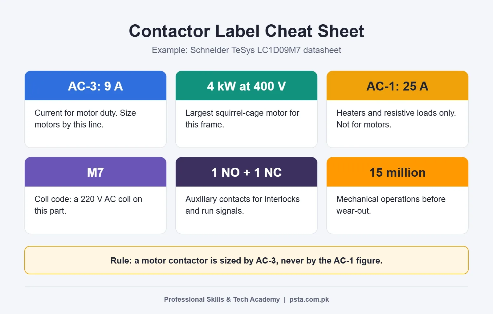
The Schneider TeSys LC1D09M7 datasheet shows what this looks like on paper. This small, very common contactor has three main poles and these ratings:
- 9 A in category AC-3 at 440 V, which suits a 4 kW motor at 380 to 400 V
- 25 A in category AC-1 for non-inductive loads
- One NO and one NC auxiliary contact built in
- 15 million mechanical operations and 2 million electrical operations at 9 A in AC-3
- Up to 3,600 operating cycles per hour
- A 220 V AC coil, which the M7 suffix denotes in this part number
Two things stand out. First, the same device carries two very different current figures depending on the load. Second, the life figures are stated for a specific category and current. A contactor's rating is always tied to how it's used.
Control.com also points out a safety benefit. If control power fails, the contactor coil drops out, the main contacts open and the load stops. The machine won't restart by itself when power returns unless the circuit is designed to do that.
Reading a Contactor Label: AC-1, AC-3 and AC-4
Relays are usually rated by a plain switching current and voltage. Contactors use utilization categories, defined in IEC/EN 60947-4-1. Lovato Electric's guide to utilization categories lists the main ones. These three cover most panel work you'll see:
| Category | Load type | Example in a Pakistani workshop |
|---|---|---|
| AC-1 | Little or no inductance, such as resistance furnaces | Heater banks in a plastic moulding machine |
| AC-3 | Squirrel-cage motors: starting, and switching off while running | Tubewell pump, blower or conveyor motor started by a DOL starter |
| AC-4 | Squirrel-cage motors with plugging and inching | Hoist or crane motor that is jogged and reversed often |
The same list also includes AC-2 for slip-ring motors, AC-5a and AC-5b for lamps, AC-6a for transformers, AC-6b for capacitor banks and AC-8a/8b for hermetic refrigerant compressors.
The trap is reading the biggest number on the label. On the LC1D09 above, 25 A is the AC-1 figure. Put a motor on it and the figure that counts is 9 A. Sizing a motor contactor by its AC-1 rating is a common error among trainees, so read the AC-3 contactor rating first.
Which One Should You Use? A Four-Question Check
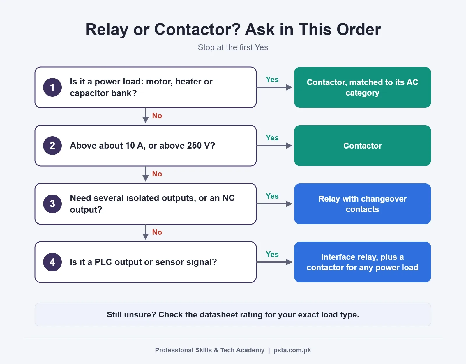
Most contactor vs relay decisions take less than a minute. Before you order a part, run through these questions in order. Stop at the first one that settles it.
- Is the load a motor, heater bank, capacitor bank or anything else on the power side? Use a contactor, and pick it by the matching utilization category.
- Does the load draw more than about 10 A, or run above 250 V? Use a contactor. Most general-purpose relays stop well short of this.
- Do you need several isolated outputs, or an NC output, from one signal? A relay with changeover contacts is usually the cleaner choice.
- Is it a PLC output, a sensor signal or a contactor coil? Use a relay as the interface, then let the relay drive the contactor coil if a power load sits behind it.
If you're unsure after these four steps, open the datasheet for the device you plan to use. Check the switching current for the exact load type, not just the headline figure.
How Do a Relay and a Contactor Share One Motor Circuit?
In real panels, contactor vs relay is rarely an either-or choice. You use both, each in its own lane. Take a pump started by a PLC as an example:
- The PLC output turns on and energizes a 24 V DC interface relay.
- The relay's NO contact closes and passes 220 V AC to the contactor coil.
- The contactor pulls in. Its three main poles connect the three phases to the motor.
- The contactor's auxiliary NO contact returns a "running" signal to a PLC input or a pilot lamp.
- An overload relay on the motor side trips when the motor stays overloaded long enough to overheat, and its NC contact opens the coil circuit.
Notice the split. The relay never carries motor current. The contactor never deals with the PLC's low-voltage signal. That separation protects the PLC, keeps the control wiring light and makes fault-finding easier, because you can test the control side and the power side one at a time.
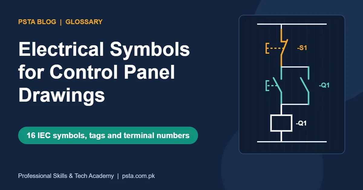
If you're new to the drawings behind this, our guide to electrical symbols for control panel drawings covers the coil, contact and overload symbols you'll meet on these schematics.
Why Forward-Reverse Starters Depend on Contactor Interlocks
Reversing a three-phase motor means swapping two phases. A forward-reverse starter does this with two contactors. If both ever close together, two phases connect straight across each other through the contactor poles.
Control.com's article on reversing contactors describes the result as a low-impedance phase-to-phase fault, not an ordinary overload. Two safeguards are used together:
- Electrical interlock: the forward contactor's NC auxiliary contact is wired in series with the reverse coil, and the reverse contactor's NC contact sits in series with the forward coil.
- Mechanical interlock: a linkage between the two contactors physically stops one closing while the other is in, whatever the control circuit does.
The same article warns that every path to either coil, including remote push buttons and PLC outputs, must pass through the opposite NC contact. A remote switch wired after that contact defeats the interlock. This is a job relays can't do on the power side, and it's a good reason to learn contactor auxiliary contacts properly. The same thinking applies when you wire a star delta starter, where the star and delta contactors must never close together.
Is an Overload Relay a Relay or a Contactor?
Neither, in the sense used above. The thermal overload relay that clips under a contactor doesn't switch the motor at all. It senses motor current through heater elements or electronics. When the current stays too high for too long, it opens its own small NC contact, which sits in the contactor's coil circuit. The coil drops out, and the contactor does the actual disconnecting.
So the overload relay is a protection device with a control contact. That's why trainees who wire it as if it breaks the motor current end up confused at the testing stage. Set its dial to the motor's nameplate full-load current, not to the contactor's rating.
It also doesn't replace short-circuit protection upstream. For that side of the panel, see our comparison of MCB vs MCCB vs RCCB.
Mistakes That Burn Out Contacts and Coils
These show up again and again in first-week lab work and in older field panels:
- Running a motor straight off a plug-in relay. Starting current and arcing wear the contacts fast. Use a contactor.
- Sizing a motor contactor by its AC-1 figure. Read the AC-3 current or the kW figure for your voltage.
- Ordering the wrong contactor coil voltage. A 24 V coil on 220 V burns out at once. A 400 V coil on 220 V may not pull in fully and will chatter. Check the coil code in the part number.
- Driving a 220 V AC contactor coil straight from a PLC transistor output. Transistor outputs switch low-voltage DC, so they can't drive that coil. Put an interface relay in between, as in the sequence above.
- Skipping the interlock on reversing circuits. One wrong button press can then cause a phase-to-phase short.
- Using AC-3 ratings for jogging duty. Frequent inching and plugging is AC-4 work and wears contacts much faster. Choose a larger frame if the duty is heavy.
Practising Contactor and Relay Wiring at PSTA
Reading a contactor vs relay comparison only gets you so far. You learn the difference properly when you wire a relay to a contactor coil, press the start button and watch which part does what. PSTA's panel wiring and PLC course is built around that kind of bench work.
According to the course page, it runs for 12 weeks at beginner level, and the current fee is Rs. 28,000. Module 2 deals with control components and protection devices, while Module 3 is about hardwired motor control circuits. The listed practicals include DOL, forward-reverse and star-delta starters, followed by VFDs, soft starters and basic PLC logic. Train on the Abbottabad campus, attend the live online classes from another city, or combine the two.
If you already know contactors and want the PLC side next, read ladder logic for beginners or our explainer on VFD vs soft starter. The full list of programs sits on the courses page. When you're ready, the admission page shows the next batch, and questions about the lab setup can go to our WhatsApp line, +92 314 5424399.
Before Your Next Panel Job: Read Two Labels
Next time you open a control panel, find one relay and one contactor. On the relay, note the coil voltage and the contact rating. On the contactor, find the AC-3 current, the kW figure for 400 V and the coil code. Then ask yourself why the designer put each device where it is. Doing that on five or six panels will teach you more about contactor vs relay choices than any table.
Frequently asked questions
Can I use a relay instead of a contactor for a small motor?
Only if the relay's datasheet gives a motor or inductive rating that covers the motor's current. Most general-purpose plug-in relays stop around 7 to 10 A and have no arc chute, so starting current wears their contacts quickly. For any three-phase motor, a small contactor such as a 9 A AC-3 frame is the safer choice.
Is a contactor just a big relay?
They work on the same coil-and-contact principle, so the comparison is fair. A contactor adds arc chutes, heavier main poles, separate auxiliary contacts and ratings by utilization category. Those features let it make and break motor and heater circuits thousands of times without the contact damage a relay would suffer.
What does AC-3 mean on a contactor?
AC-3 is a utilization category from IEC/EN 60947-4-1. It covers squirrel-cage motors that are started and switched off while running, which describes most pump, fan and conveyor motors. The AC-3 current and kW figures on the label are the ones to use when you size a contactor for a motor.
Why does my contactor buzz or chatter?
Common causes are a coil voltage that doesn't match the supply, low control voltage during heavy load, a loose control wire, or dirt on the iron core faces. Measure the voltage at the coil terminals while it is energized and compare it with the coil code. Replace a coil that has overheated or changed color.
Do I need an overload relay with every contactor?
For motor circuits, yes. The contactor only switches; it doesn't sense overload. A thermal or electronic overload relay watches motor current and opens the coil circuit if the motor runs too hot. Set it to the motor's full-load current from the nameplate, and keep short-circuit protection such as an MCB or MCCB upstream.
Can a PLC drive a contactor coil directly?
A relay-output PLC can often switch a small contactor coil if the coil current is within the output rating. Transistor outputs switch low-voltage DC, so a 220 V AC coil needs an interface relay between them. An interface relay also protects the PLC output card if the contactor coil fails.
Which is better for a home inverter or UPS changeover?
For a household changeover that carries only a few amps, a correctly rated power relay may be enough. If the changeover carries a whole house load, air conditioners or a motor-driven pump, use a contactor or a proper changeover switch rated for that current. Always check the rating for the actual load type.
Sources & references
- Difference Between Relay and Contactor (Schneider Electric) eshop.se.com
- Contactors Versus Relays: Differences and Applications (Control.com) control.com
- What Is the Utilization Category of a Contactor? (Lovato Electric) academy.lovatoelectric.com
- TeSys Deca LC1D09M7 Product Datasheet (Schneider Electric) cdn.erply.com
- Finder 55 Series Plug-In Relay, 230 V AC Coil, 7 A (RS) uk.rs-online.com
- Reversing Motor Contactors: Interlocking Methods (Control.com) control.com
Last reviewed & updated on by Umar Qureshi. Written by the PSTA team in Abbottabad, Pakistan.

Umar Qureshi

Master Industrial Automation: Single & Three-Phase Panel Wiring, PLC & VFD Certification
Turn this guide into a career: hands-on training with real projects, online across Pakistan or on-campus in Abbottabad · 3 Months (12 Weeks).

Comments
No comments yet — ask a question or share your experience.